
Coretech Innovations
Coretech Innovations


Coretech Innovations' E-Mobility Lab develops AI, IoT, Embedded Systems, R&D,Robotics, EV simulators, and Wallbox chargers for EV cars.


At Coretech Innovations, we specialize in embedded software development tailored to meet the unique needs of your projects. Our expert team combines extensive experience in both software and hardware to deliver high-performance solutions for a wide range of tech industry, including automotive, consumer electronics, and industrial automation.
At Coretech Innovations, we specialize in developing high-quality web and mobile applications tailored to meet your unique business needs. Our team of experienced developers focuses on creating intuitive, user-friendly interfaces and robust backend systems, ensuring seamless performance across various platforms. We prioritize best practices in design, coding, and testing, utilizing the latest technologies and frameworks to deliver secure, scalable, and responsive applications. Whether you need a feature-rich web app or a dynamic mobile experience, our commitment to excellence ensures that your digital solutions are both innovative and reliable, providing a superior user experience.
At Coretech Innovations, we offer comprehensive software system testing services aligned with ISTQB standards and functional safety standards, such as ISO 26262. Our testing processes ensure high-quality, reliable, and safe software systems. We leverage automation tools and Continuous Integration/Continuous Deployment (CI/CD) pipelines, including Jenkins, to streamline testing and deployment. This approach enables us to provide rapid feedback, efficient bug detection, and consistent quality assurance, ensuring your software meets the highest industry and regulatory standards while accelerating time-to-market.
Coretech Innovations offers comprehensive software maintenance services designed to keep your systems running smoothly and efficiently. Our services include regular updates, bug fixes, performance optimization, and security enhancements, ensuring that your software remains robust and secure. We also provide technical support and troubleshooting, helping to minimize downtime and address issues promptly. By partnering with us, you can extend the lifespan of your software, reduce operational risks, and focus on your core business activities while we handle the technical complexities.
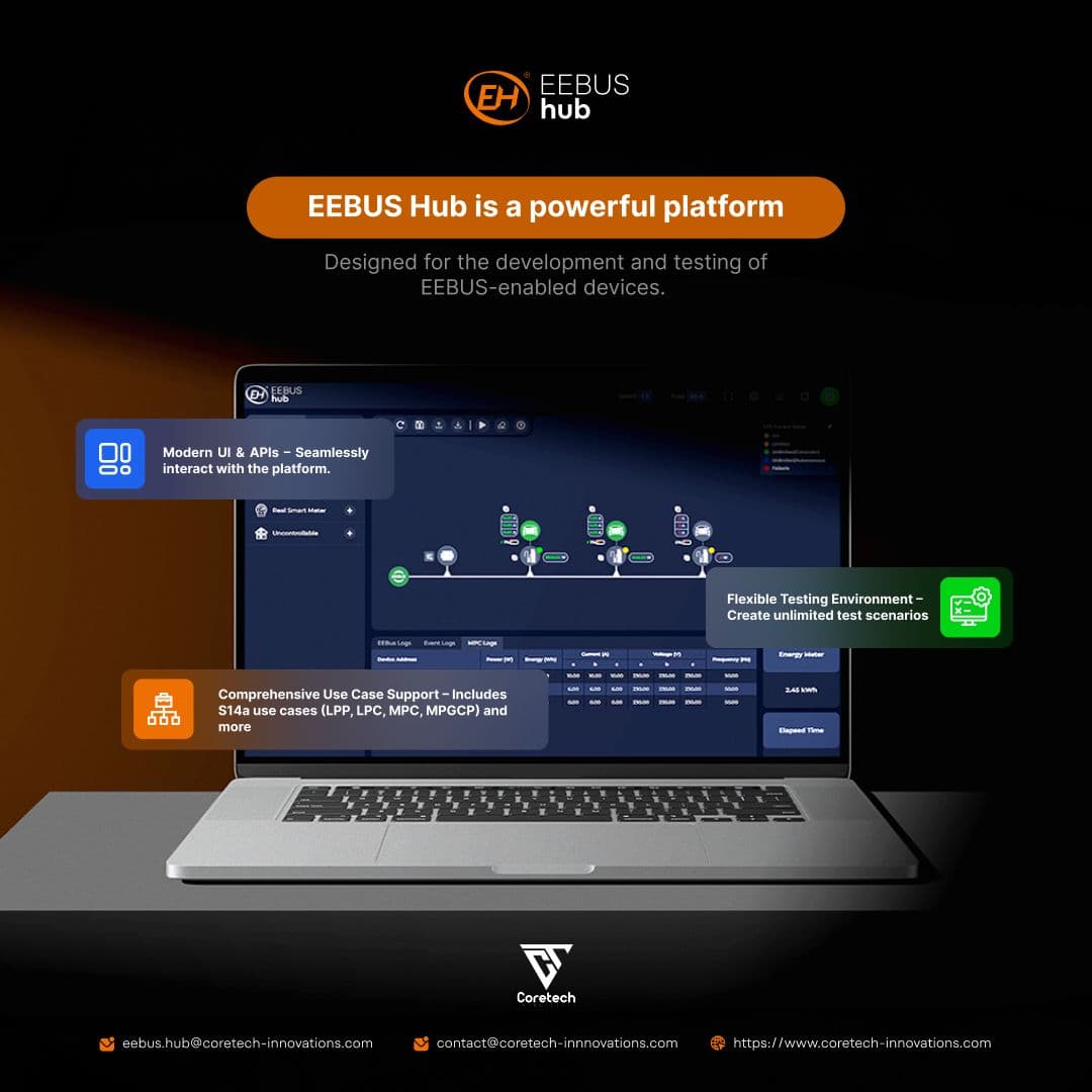
Accelerate your EEBUS device development process and streamline your workflow with EEBUS-Hub, the cutting-edge framework designed to seamlessly integrate your devices over an EEBUS network. Whether you’re working with Software in the Loop (SiL) or Hardware in the Loop (HiL) scenarios, EEBUS-Hub provides robust support to ensure flawless performance and compatibility. Read More


Learn how our innovative solutions are solving real-world challenges in the EV software industry. Your journey to understanding starts here !

Electric vehicles (EVs) have gained immense popularity over recent years, and with their rise comes the necessity to understand the intricacies of EV charging. Charging an EV isn't as straightforward as plugging it into any socket; instead, there are technicalities and specifications that need consideration, particularly when it comes to the type of current being used.
The Difference Between AC and DC Charging
Firstly, let's clear a common misconception: batteries can never be charged directly using AC power. Batteries inherently need direct current (DC) for charging. When you use an AC charger, it essentially supplies alternating current to the vehicle. However, since the battery needs DC, vehicles are equipped with an AC-DC converter to change the power type. On the other hand, DC chargers supply the required DC current directly to the vehicle, bypassing the need for conversion as the AC-DC converter is integrated within the charger itself.
Levels of EV Charging
There are primarily three levels of EV charging based on the voltage and the corresponding charging time:
1. Level 1 (AC - 120 V)
- Uses a regular household outlet.
- Commonly installed at residences for overnight charging.
- Typically takes up to 20 hours to fully charge a battery.
- Costs range between $200 to $500, excluding installation fees.
2. Level 2 (AC - 240 V)
- Requires specialized charging stations.
- Found at both public places and private homes.
- Charging duration varies between 4 to 8 hours, contingent on battery size.
- Priced between $500 to $2000 plus installation expenses.
3. Level 3 (DC - 480 V)
- Employs a minimum of 480 V (DC EVSE).
- Predominantly situated in public locations for quick charging.
- Can charge a battery within a swift 20 to 30 minutes.
- Starting price is around $5000, not including installation.
AC vs. DC Charging: A Comparative Analysis
When assessing AC against DC charging, charging speed is the evident distinction. AC chargers, providing a power output ranging from 7 KW to 22 KW, are relatively slower. For instance, a 40 KWH battery in a Nissan Leaf requires 6 hours with a 7 KW AC charger, potentially increasing to 8 hours for larger batteries.
Contrarily, DC chargers are considerably more efficient. Their power output spans from 50 to 350 KW. The aforementioned Nissan Leaf’s 40 KWh battery can be replenished in a mere 15 minutes when using a DC charger. However, DC chargers are substantially bulkier due to the presence of components like transformers, rectifiers, power factor correction units, and cooling systems.
In Conclusion
The world of EV charging presents a blend of technology, convenience, and speed. While AC chargers are more suitable for home-based, overnight charging, DC chargers cater to those on the go, offering a rapid power boost. As electric vehicles become the norm, understanding the intricacies of their charging processes becomes essential for prospective and current EV owners.
Electric Vehicles
Electric vehicles (EVs) have gained immense popularity over recent years, and with their rise comes the necessity to understand the intricacies of EV charging. Charging an EV isn't as straightforward as plugging it into any socket; instead, there are technicalities and specifications that need consideration, particularly when it comes to the type of current being used.
The Difference Between AC and DC Charging
Firstly, let's clear a common misconception: batteries can never be charged directly using AC power. Batteries inherently need direct current (DC) for charging. When you use an AC charger, it essentially supplies alternating current to the vehicle. However, since the battery needs DC, vehicles are equipped with an AC-DC converter to change the power type. On the other hand, DC chargers supply the required DC current directly to the vehicle, bypassing the need for conversion as the AC-DC converter is integrated within the charger itself.
Levels of EV Charging
There are primarily three levels of EV charging based on the voltage and the corresponding charging time:
1. Level 1 (AC - 120 V)
- Uses a regular household outlet.
- Commonly installed at residences for overnight charging.
- Typically takes up to 20 hours to fully charge a battery.
- Costs range between $200 to $500, excluding installation fees.
2. Level 2 (AC - 240 V)
- Requires specialized charging stations.
- Found at both public places and private homes.
- Charging duration varies between 4 to 8 hours, contingent on battery size.
- Priced between $500 to $2000 plus installation expenses.
3. Level 3 (DC - 480 V)
- Employs a minimum of 480 V (DC EVSE).
- Predominantly situated in public locations for quick charging.
- Can charge a battery within a swift 20 to 30 minutes.
- Starting price is around $5000, not including installation.
AC vs. DC Charging: A Comparative Analysis
When assessing AC against DC charging, charging speed is the evident distinction. AC chargers, providing a power output ranging from 7 KW to 22 KW, are relatively slower. For instance, a 40 KWH battery in a Nissan Leaf requires 6 hours with a 7 KW AC charger, potentially increasing to 8 hours for larger batteries.
Contrarily, DC chargers are considerably more efficient. Their power output spans from 50 to 350 KW. The aforementioned Nissan Leaf’s 40 KWh battery can be replenished in a mere 15 minutes when using a DC charger. However, DC chargers are substantially bulkier due to the presence of components like transformers, rectifiers, power factor correction units, and cooling systems.
In Conclusion
The world of EV charging presents a blend of technology, convenience, and speed. While AC chargers are more suitable for home-based, overnight charging, DC chargers cater to those on the go, offering a rapid power boost. As electric vehicles become the norm, understanding the intricacies of their charging processes becomes essential for prospective and current EV owners.

In the realm of software safety, particularly in automotive applications, error handling is a pivotal aspect. Just as electric vehicles have revolutionized transportation, error-handling mechanisms have transformed software reliability. These mechanisms, guided by ISO 26262 standards, are not just about detecting errors; they encompass a comprehensive approach to manage and mitigate software failures.
Different Types of Error Handling Mechanisms
Error handling in software systems, akin to charging an electric vehicle, is not a one-size-fits-all solution. Depending on the type of error and the required Automotive Safety Integrity Level (ASIL), different mechanisms come into play.
1. Plausibility Checks
- Similar to assessing the compatibility of an EV charger, plausibility checks ensure data validity.
- Critical in preempting erroneous operations by verifying data against expected ranges.
2. Substitute Values
- Substitute values act like an emergency power supply, providing backup data during errors.
- They ensure system functionality, albeit at a reduced level, enhancing safety.
3. Voting Mechanisms
- In these systems, multiple inputs are compared, akin to selecting the optimal charging method for efficiency.
- Voting is crucial in high-redundancy systems, ensuring decision accuracy.
4. Checksums/Codes
- Checksums and codes are like the safety checks in EV charging, ensuring data integrity.
- They play a vital role in detecting and correcting errors in data transmission.
Aligning Error Mechanisms with ISO 26262 Standards
Just as EV charging levels vary in voltage and speed, error handling mechanisms differ in complexity and application based on the ASIL requirements. High ASIL levels demand more robust and sophisticated error handling strategies, akin to faster, more powerful EV chargers. This alignment ensures that the software meets the stringent safety requirements critical in automotive applications.
In Conclusion
Error handling mechanisms in software systems, governed by ISO 26262 standards, are as diverse and complex as the world of EV charging. From plausibility checks to sophisticated voting mechanisms, each plays a unique role in ensuring software reliability and safety. As software continues to drive automotive innovation, understanding these mechanisms becomes crucial, just as understanding EV charging is vital for electric vehicle users.
Error Handling in Software Systems: An ISO 26262 Perspective
In the realm of software safety, particularly in automotive applications, error handling is a pivotal aspect. Just as electric vehicles have revolutionized transportation, error-handling mechanisms have transformed software reliability. These mechanisms, guided by ISO 26262 standards, are not just about detecting errors; they encompass a comprehensive approach to manage and mitigate software failures.
Different Types of Error Handling Mechanisms
Error handling in software systems, akin to charging an electric vehicle, is not a one-size-fits-all solution. Depending on the type of error and the required Automotive Safety Integrity Level (ASIL), different mechanisms come into play.
1. Plausibility Checks
- Similar to assessing the compatibility of an EV charger, plausibility checks ensure data validity.
- Critical in preempting erroneous operations by verifying data against expected ranges.
2. Substitute Values
- Substitute values act like an emergency power supply, providing backup data during errors.
- They ensure system functionality, albeit at a reduced level, enhancing safety.
3. Voting Mechanisms
- In these systems, multiple inputs are compared, akin to selecting the optimal charging method for efficiency.
- Voting is crucial in high-redundancy systems, ensuring decision accuracy.
4. Checksums/Codes
- Checksums and codes are like the safety checks in EV charging, ensuring data integrity.
- They play a vital role in detecting and correcting errors in data transmission.
Aligning Error Mechanisms with ISO 26262 Standards
Just as EV charging levels vary in voltage and speed, error handling mechanisms differ in complexity and application based on the ASIL requirements. High ASIL levels demand more robust and sophisticated error handling strategies, akin to faster, more powerful EV chargers. This alignment ensures that the software meets the stringent safety requirements critical in automotive applications.
In Conclusion
Error handling mechanisms in software systems, governed by ISO 26262 standards, are as diverse and complex as the world of EV charging. From plausibility checks to sophisticated voting mechanisms, each plays a unique role in ensuring software reliability and safety. As software continues to drive automotive innovation, understanding these mechanisms becomes crucial, just as understanding EV charging is vital for electric vehicle users.

In the dynamic world of software development, understanding the intricacies of frameworks is key to efficient programming. One such feature, essential for Qt developers, is the Signals and Slots mechanism. This article delves into its nuances, offering insights into how it revolutionizes object communication in Qt.
What is the Qt Signal and Slot Mechanism?
The Qt Signals and Slots mechanism facilitates communication between objects, which can be in the same thread, different threads, or even different processes. It operates by having Object A emit a signal in response to an event, and Object B, or multiple objects, react by executing a slot (function). This setup is integral for responsive and dynamic applications.
Advantages of the Mechanism
- Ease of Use: Connecting a signal to a slot requires minimal syntax, often just a single line of code.
- Flexibility: It supports various communication patterns, like one-to-one, one-to-many, and many-to-one connections.
- Dynamic Connections: Signals and slots can be connected or disconnected at runtime, adding versatility.
- Asynchronous Communication: This feature facilitates non-blocking operations, essential for modern, responsive applications.
- Loose Coupling: The sender and receiver are unaware of each other’s existence, promoting modular code design.
Connection Types
1. Direct Connection: The slot executes in the emitter’s thread, which can block the thread until execution completes.
2. Queued Connection: Allows the emitter’s thread to continue its event loop, with the slot executing in the receiver’s thread.
Usage and Syntax
The syntax for connecting a signal to a slot is straightforward:
cpp
QObject::connect(sender, SIGNAL(signalName(parameters)), receiver, SLOT(slotName(parameters)));
This simplicity underscores Qt’s user-friendly approach to complex communication patterns.
Practical Use Case
Consider a Modem Manager in an application interfacing with a user interface (UI). When the Modem State changes, the UI needs to update accordingly. Using Qt’s mechanism, the Modem Manager emits a signal upon state change, and the UI's slot updates the display. This demonstrates the mechanism's ability to handle real-time data updates in applications.
Common Pitfalls
While powerful, this mechanism requires attention to detail. Mismatched signal and slot arguments can lead to runtime errors, highlighting the importance of precise implementation.
Conclusion
Qt's Signals and Slots mechanism is a cornerstone for efficient and dynamic object communication in applications. Its ease of use, coupled with the flexibility it offers, makes it an invaluable tool for developers. Whether you’re a seasoned Qt programmer or new to the framework, mastering this mechanism is crucial for creating responsive, modular, and robust applications.
QT Communications
In the dynamic world of software development, understanding the intricacies of frameworks is key to efficient programming. One such feature, essential for Qt developers, is the Signals and Slots mechanism. This article delves into its nuances, offering insights into how it revolutionizes object communication in Qt.
What is the Qt Signal and Slot Mechanism?
The Qt Signals and Slots mechanism facilitates communication between objects, which can be in the same thread, different threads, or even different processes. It operates by having Object A emit a signal in response to an event, and Object B, or multiple objects, react by executing a slot (function). This setup is integral for responsive and dynamic applications.
Advantages of the Mechanism
- Ease of Use: Connecting a signal to a slot requires minimal syntax, often just a single line of code.
- Flexibility: It supports various communication patterns, like one-to-one, one-to-many, and many-to-one connections.
- Dynamic Connections: Signals and slots can be connected or disconnected at runtime, adding versatility.
- Asynchronous Communication: This feature facilitates non-blocking operations, essential for modern, responsive applications.
- Loose Coupling: The sender and receiver are unaware of each other’s existence, promoting modular code design.
Connection Types
1. Direct Connection: The slot executes in the emitter’s thread, which can block the thread until execution completes.
2. Queued Connection: Allows the emitter’s thread to continue its event loop, with the slot executing in the receiver’s thread.
Usage and Syntax
The syntax for connecting a signal to a slot is straightforward:
cpp
QObject::connect(sender, SIGNAL(signalName(parameters)), receiver, SLOT(slotName(parameters)));
This simplicity underscores Qt’s user-friendly approach to complex communication patterns.
Practical Use Case
Consider a Modem Manager in an application interfacing with a user interface (UI). When the Modem State changes, the UI needs to update accordingly. Using Qt’s mechanism, the Modem Manager emits a signal upon state change, and the UI's slot updates the display. This demonstrates the mechanism's ability to handle real-time data updates in applications.
Common Pitfalls
While powerful, this mechanism requires attention to detail. Mismatched signal and slot arguments can lead to runtime errors, highlighting the importance of precise implementation.
Conclusion
Qt's Signals and Slots mechanism is a cornerstone for efficient and dynamic object communication in applications. Its ease of use, coupled with the flexibility it offers, makes it an invaluable tool for developers. Whether you’re a seasoned Qt programmer or new to the framework, mastering this mechanism is crucial for creating responsive, modular, and robust applications.

Release 1.2.0 Highlights
- Support Grid Use Cases (LPC,LPP, MGCP and MPC)
- Support Inverter Integration as Hardware in the Loop Test Device
- EEBUS Device Finder over Network
- EEBUS New Release Notifier
- Updated EEBUS EMS Control Logic
- Release EEBUS Hub Docker Image
- Added More Examples and Demos
You can download the eebus from https://www.coretech-innovations.com/products/eebushub/download
Support Grid Use Cases
Limitation of Power Consumption (LPC)
Supported Scenarios
- Control active power consumption Limit
- Failsafe Values
- Heartbeat
- Constraints
Support Grid Use Cases
Limitation of Power Consumption (LPC)
Supported LPC Devices
- Energy Guard
- Controllable System
- Showcase of LPC automated testing : https://github.com/Coretech-Innovations/EEBus-Hub/tree/main/examples/Api/LPC
Support Grid Use Cases
Limitation of Power Consumption (LPC)
New APIs Overview
- Several new APIs to interact with the newly supported use cases.
- Grid Use Cases APIs example :
- Send LPC command
- Endpoint:"/cem/ActivePowerConsumptionLimit/:deviceAddress"
- Method:POST
- Purpose:Trigger the Energy Guard to send a specified limit command to a connected controllable system. The route also provides a response indicating whether the controllable system approves or denies the command.
- 3. All APIs for the EEBus-Hub is documented and could be found Here https://github.com/Coretech-Innovations/EEBus-Hub/blob/main/docs/eebus-hub.yaml.
EEBUS Network Discovery
- Pairing the Device
- Select an EVSE to enable the simulated EMS to trust the EVSE's SKI code
- Initiate the secure pairing process by starting the simulation.
- Discovering Devices
- Automatically categorize devices found on the local network for intuitive scanning.
- Searching Made Simple
- Use the improved filter tool for efficient identification of specific devices.
EEBUS New Release Notifier
New Release Notifier: Always stay up to date with notifications for new releases integrated into the EEBUS-Hub.
Supported EEBUS Use Cases
- E-Mobility
- Overload Protection by EV Charging Curtailment
- EVSE Commissioning and Configuration
- EV State of Charge
- EV Comissioning and Configuration
- EV Charging Electricity Measurement
- Grid
- Limitation of Power Consumption
- Monitoring of Grid Connection Point
- Limitation of Power Production
- Monitoring of Power Consumption
Planned EEBUS Hub Features
EEBUS-Hub V1.2.0
Release 1.2.0 Highlights
- Support Grid Use Cases (LPC,LPP, MGCP and MPC)
- Support Inverter Integration as Hardware in the Loop Test Device
- EEBUS Device Finder over Network
- EEBUS New Release Notifier
- Updated EEBUS EMS Control Logic
- Release EEBUS Hub Docker Image
- Added More Examples and Demos
You can download the eebus from https://www.coretech-innovations.com/products/eebushub/download
Support Grid Use Cases
Limitation of Power Consumption (LPC)
Supported Scenarios
- Control active power consumption Limit
- Failsafe Values
- Heartbeat
- Constraints
Support Grid Use Cases
Limitation of Power Consumption (LPC)
Supported LPC Devices
- Energy Guard
- Controllable System
- Showcase of LPC automated testing : https://github.com/Coretech-Innovations/EEBus-Hub/tree/main/examples/Api/LPC
Support Grid Use Cases
Limitation of Power Consumption (LPC)
New APIs Overview
- Several new APIs to interact with the newly supported use cases.
- Grid Use Cases APIs example :
- Send LPC command
- Endpoint:"/cem/ActivePowerConsumptionLimit/:deviceAddress"
- Method:POST
- Purpose:Trigger the Energy Guard to send a specified limit command to a connected controllable system. The route also provides a response indicating whether the controllable system approves or denies the command.
- 3. All APIs for the EEBus-Hub is documented and could be found Here https://github.com/Coretech-Innovations/EEBus-Hub/blob/main/docs/eebus-hub.yaml.
EEBUS Network Discovery
- Pairing the Device
- Select an EVSE to enable the simulated EMS to trust the EVSE's SKI code
- Initiate the secure pairing process by starting the simulation.
- Discovering Devices
- Automatically categorize devices found on the local network for intuitive scanning.
- Searching Made Simple
- Use the improved filter tool for efficient identification of specific devices.
EEBUS New Release Notifier
New Release Notifier: Always stay up to date with notifications for new releases integrated into the EEBUS-Hub.
Supported EEBUS Use Cases
- E-Mobility
- Overload Protection by EV Charging Curtailment
- EVSE Commissioning and Configuration
- EV State of Charge
- EV Comissioning and Configuration
- EV Charging Electricity Measurement
- Grid
- Limitation of Power Consumption
- Monitoring of Grid Connection Point
- Limitation of Power Production
- Monitoring of Power Consumption
Planned EEBUS Hub Features

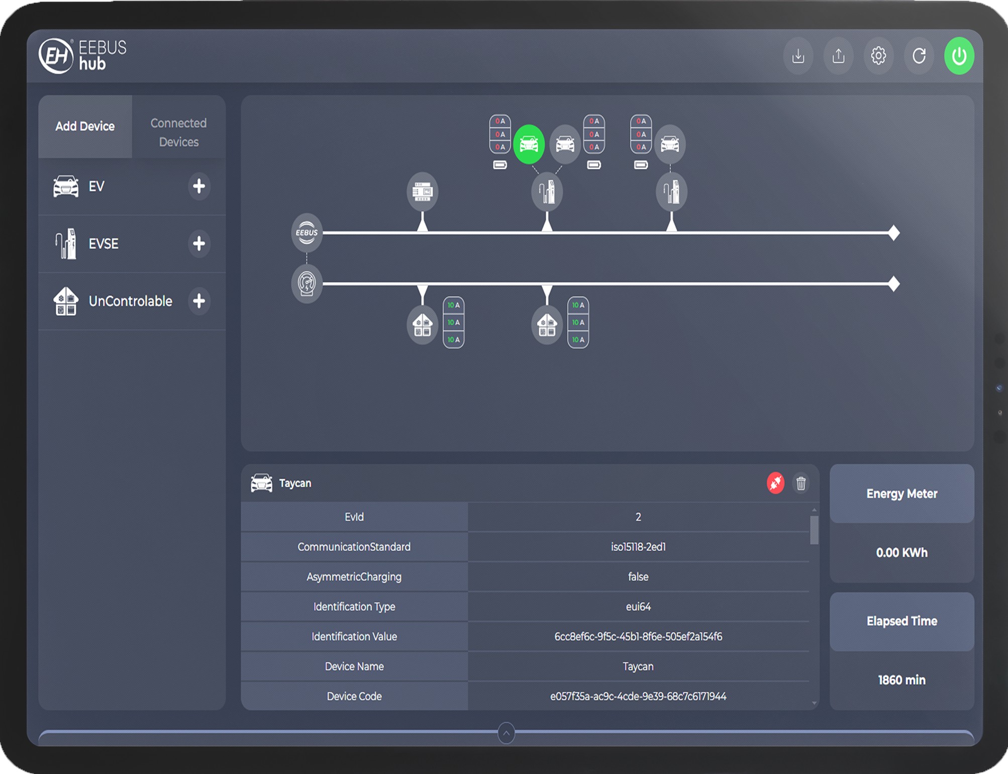
EEBUS-Hub
Your Ultimate EEBUS HiL/SiL Testing Framework
Overview
- A framework for building and testing your device’s EEBUS Stack, enabling interaction with various devices.
- Provides APIs and a UI to control various actors participating in an EEBUS environment, such as EVs, EVSEs, HEMS, Energy Guards, and SMGWs.
- The simulation allows for the integration of real devices (HiL) alongside numerous simulated devices, facilitating the testing of an EEBUS device.
Motive
EEBUS-Hub is intended to be a catalyst to integrating EEBUS stack in your device i.e
Supported Devices
EEBUS-Hub Supports the following devices:
- EVs
- EVSE
- CEM / HEMS
- Home Fuse Limits & Available Grid Feed Power
Hardware in the Loop Support
EEBUS-Hub Supports plugging real hardware into the simulation so that you can test your device interaction with other devices over different use cases and scenarios.
E.g. You can either plug your own CEM or EVSE into the simulation
Built for CICD
- Scenarios could be designed using UI or using API base approach
- EEBUS has Conformance and compliance testing against EEBUS standards to ensure your device compliance
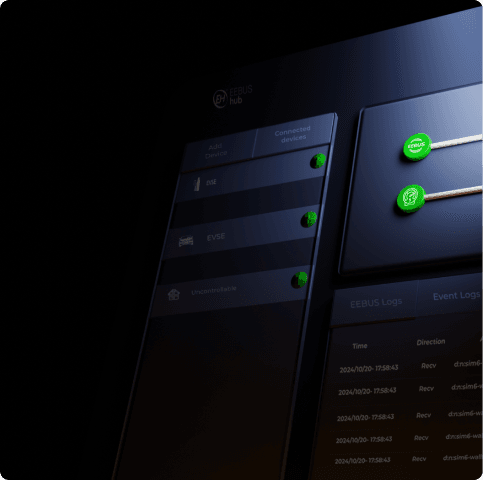
EEBUS Messages Logging
- Supports logging EEBUS messages so that you can catch debug your system interactions easily
- Logs could be dumped to csv files or it could be visualized using EEBUS-Hub Viewer.
Supported EEBUS Use Cases
1. E-Mobility
- Overload Protection by EV Charging Curtailment
- EV State of Charge
- EV Comissioning and Configuration
- EVSE Commissioning and Configuration
- EV Charging Electricity Measurement
2. Grid
- Limitation of Power Consumption
- Limitation of Power Production
- Monitoring of Grid Connection Point
- Monitoring of Power Consumption
Summary
- SiL: Framework to build a full EEBUS setup without the need of any external hardware
- UI : Additional UI to facilitate simulation scenario design
- Plug & Play : For real hardware insertion in the environment (HiL)
- Configurable : off the shelf electrical devices with EEBUS interface (EV,EVSE,CEM,SMGW,.....)
- Free Licence : Binary is licensed under GPLv2
- Compliance test suite : to ensure a device is compliant with the EEBUS standard
- API : APIs to add, remove, configure or query the simulation environment
- EEBUS : EEBUS messages Logging
Applications
- CICD
- HiL Testing
- Rapid Prototyping - SiL
- EEBUS Compliance Testing
APIs
- EEBus-Hub is programming language agnostic as all control is performed via APIs
- In the future an SDK will be supplied for this API over Python and GO, but for now using the API makes the simulator very accessible.
UI Interface
EEBUS-Hub
EEBUS-Hub
Your Ultimate EEBUS HiL/SiL Testing Framework
Overview
- A framework for building and testing your device’s EEBUS Stack, enabling interaction with various devices.
- Provides APIs and a UI to control various actors participating in an EEBUS environment, such as EVs, EVSEs, HEMS, Energy Guards, and SMGWs.
- The simulation allows for the integration of real devices (HiL) alongside numerous simulated devices, facilitating the testing of an EEBUS device.
Motive
EEBUS-Hub is intended to be a catalyst to integrating EEBUS stack in your device i.e
Supported Devices
EEBUS-Hub Supports the following devices:
- EVs
- EVSE
- CEM / HEMS
- Home Fuse Limits & Available Grid Feed Power
Hardware in the Loop Support
EEBUS-Hub Supports plugging real hardware into the simulation so that you can test your device interaction with other devices over different use cases and scenarios.
E.g. You can either plug your own CEM or EVSE into the simulation
Built for CICD
- Scenarios could be designed using UI or using API base approach
- EEBUS has Conformance and compliance testing against EEBUS standards to ensure your device compliance
EEBUS Messages Logging
- Supports logging EEBUS messages so that you can catch debug your system interactions easily
- Logs could be dumped to csv files or it could be visualized using EEBUS-Hub Viewer.
Supported EEBUS Use Cases
1. E-Mobility
- Overload Protection by EV Charging Curtailment
- EV State of Charge
- EV Comissioning and Configuration
- EVSE Commissioning and Configuration
- EV Charging Electricity Measurement
2. Grid
- Limitation of Power Consumption
- Limitation of Power Production
- Monitoring of Grid Connection Point
- Monitoring of Power Consumption
Summary
- SiL: Framework to build a full EEBUS setup without the need of any external hardware
- UI : Additional UI to facilitate simulation scenario design
- Plug & Play : For real hardware insertion in the environment (HiL)
- Configurable : off the shelf electrical devices with EEBUS interface (EV,EVSE,CEM,SMGW,.....)
- Free Licence : Binary is licensed under GPLv2
- Compliance test suite : to ensure a device is compliant with the EEBUS standard
- API : APIs to add, remove, configure or query the simulation environment
- EEBUS : EEBUS messages Logging
Applications
- CICD
- HiL Testing
- Rapid Prototyping - SiL
- EEBUS Compliance Testing
APIs
- EEBus-Hub is programming language agnostic as all control is performed via APIs
- In the future an SDK will be supplied for this API over Python and GO, but for now using the API makes the simulator very accessible.
UI Interface
Limitation of Power Consumption Using EEBUS Hub
EEBUS-Hub now supports the EEBUS LPC (Limitation of Power Consumption) use case in both server and client modes! This enhancement ensures that your device's § 14a compliance is achieved faster and more efficiently, accelerating interoperability testing and enabling the development of diverse and complex scenarios. Additionally, EEBUS-Hub allows you to seamlessly integrate test scenarios into CICD environments.
Use Case Demo Setup
Description
Simulate sending EEBUS LPC command using EEBUS-Hub energy guard and visualize the response of the controllable system (DUT)
The controllable system in this demo is a 3-phase wallbox charger with the following current limitations:
- Minimum: 6A per phase (4,140W on all phases)
- Minimum: 16A per phase (11,040W on all phases)
Demo Steps In Details
How Can We Help You with your EEBUS Product?
- EEBUS Stack Integration Support
- CICD Pipelines Setup
- EEBUS Compliance Testing
- Tooling & Automation
- Traning & Consultation
Our Comprehensive Services
EEBUS Hub LPC
Limitation of Power Consumption Using EEBUS Hub
EEBUS-Hub now supports the EEBUS LPC (Limitation of Power Consumption) use case in both server and client modes! This enhancement ensures that your device's § 14a compliance is achieved faster and more efficiently, accelerating interoperability testing and enabling the development of diverse and complex scenarios. Additionally, EEBUS-Hub allows you to seamlessly integrate test scenarios into CICD environments.
Use Case Demo Setup
Description
Simulate sending EEBUS LPC command using EEBUS-Hub energy guard and visualize the response of the controllable system (DUT)
The controllable system in this demo is a 3-phase wallbox charger with the following current limitations:
- Minimum: 6A per phase (4,140W on all phases)
- Minimum: 16A per phase (11,040W on all phases)
Demo Steps In Details
How Can We Help You with your EEBUS Product?
- EEBUS Stack Integration Support
- CICD Pipelines Setup
- EEBUS Compliance Testing
- Tooling & Automation
- Traning & Consultation
Our Comprehensive Services

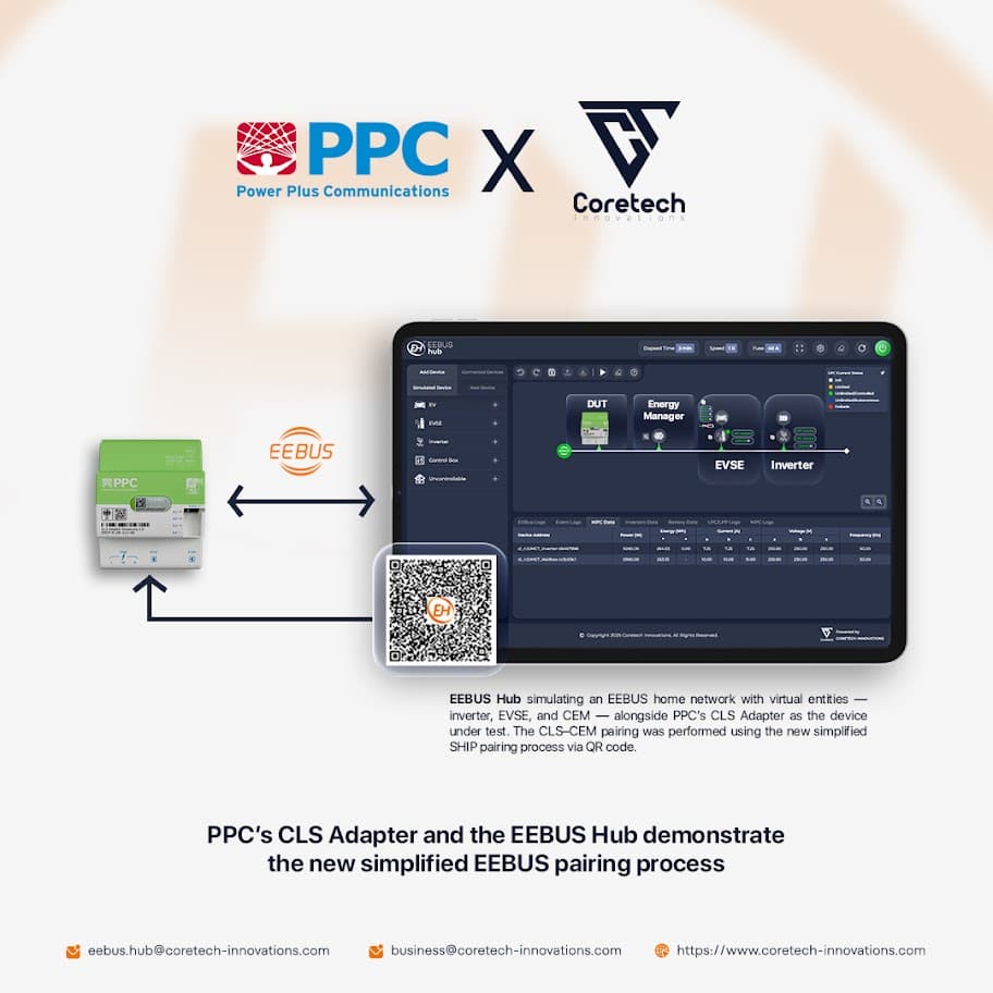
PPCs CLS Adapter und der EEBUS Hub demonstrieren den neuen vereinfachten EEBUS-Pairing-Prozess
Wir freuen uns, eine erfolgreiche Interoperabilität zwischen dem PPC CLS Adapter (Nutzung vom KEO EEBUS Stack) und dem EEBUS Hub (betrieben durch eebus-go Open Source Stack) bekanntzugeben.
Gemeinsam haben wir gezeigt, wie interoperabel der neue vereinfachte Pairing-Prozess Geräte schneller, zuverlässiger und mit deutlich weniger Aufwand in Betrieb nimmt.
Was haben wir erreicht?
- Erfolgreiches SHIP-Pairing mit dem neuen vereinfachten Installationsverfahren für eine schnelle und einfache Inbetriebnahme
- Verifizierung der Interoperabilität von Grid-Use-Cases (LPC und LPP)
- Nachweis echter Interoperabilität über verschiedene Stacks hinweg – EEBUS Hub (eebus-go) und PPC CLS Adapter (KEO Stack)
- Beschleunigte Validierung mit dem EEBUS Hub – Testen komplexer Konstellationen und Use-Cases zur Verkürzung der Entwicklungszyklen
- Der EEBUS Hub wurde entwickelt, um Herstellern Entwicklung und Testing zu erleichtern – und damit die EEBUS-Adoption voranzutreiben. Dieses Showcase ist ein Beispiel für seine Vielseitigkeit in echten Interoperabilitätsszenarien.
- Sind Sie dabei? Kommen Sie vorbei und erleben Sie, wie der EEBUS Hub Herstellern hilft, Geräte schneller interoperabel und marktreif zu machen.
Möchten Sie Ihre EEBUS-Entwicklungen beschleunigen?
Kontaktieren Sie uns:
eebus.hub@coretech-innovations.com
#SeeYouAtPlugfest — lassen Sie uns EEBUS gemeinsam zum Erfolg machen!
Reference: LinkedIn Post
EEBUS Hub und PPC CLS Adapter im Zusammenspiel
PPCs CLS Adapter und der EEBUS Hub demonstrieren den neuen vereinfachten EEBUS-Pairing-Prozess
Wir freuen uns, eine erfolgreiche Interoperabilität zwischen dem PPC CLS Adapter (Nutzung vom KEO EEBUS Stack) und dem EEBUS Hub (betrieben durch eebus-go Open Source Stack) bekanntzugeben.
Gemeinsam haben wir gezeigt, wie interoperabel der neue vereinfachte Pairing-Prozess Geräte schneller, zuverlässiger und mit deutlich weniger Aufwand in Betrieb nimmt.
Was haben wir erreicht?
- Erfolgreiches SHIP-Pairing mit dem neuen vereinfachten Installationsverfahren für eine schnelle und einfache Inbetriebnahme
- Verifizierung der Interoperabilität von Grid-Use-Cases (LPC und LPP)
- Nachweis echter Interoperabilität über verschiedene Stacks hinweg – EEBUS Hub (eebus-go) und PPC CLS Adapter (KEO Stack)
- Beschleunigte Validierung mit dem EEBUS Hub – Testen komplexer Konstellationen und Use-Cases zur Verkürzung der Entwicklungszyklen
- Der EEBUS Hub wurde entwickelt, um Herstellern Entwicklung und Testing zu erleichtern – und damit die EEBUS-Adoption voranzutreiben. Dieses Showcase ist ein Beispiel für seine Vielseitigkeit in echten Interoperabilitätsszenarien.
- Sind Sie dabei? Kommen Sie vorbei und erleben Sie, wie der EEBUS Hub Herstellern hilft, Geräte schneller interoperabel und marktreif zu machen.
Möchten Sie Ihre EEBUS-Entwicklungen beschleunigen?
Kontaktieren Sie uns:
eebus.hub@coretech-innovations.com
#SeeYouAtPlugfest — lassen Sie uns EEBUS gemeinsam zum Erfolg machen!
Reference: LinkedIn Post
We are pleased to welcome Coretech Innovations as a new member of the EEBUS Initiative.
Coretech Innovations is a fast-growing software services company dedicated to advancing interoperability and standardised communication in the energy sector. Their work focuses on helping manufacturers integrate EEBUS efficiently and reliably, drawing on strong expertise in development, testing, and system integration.
With a team experienced in EEBUS and software engineering, Coretech brings both technical expertise and practical industry knowledge. This background enables them to support manufacturers in simplifying integration, meeting regulatory requirements, and advancing innovation.
By joining EEBus e.V., Coretech Innovations contributes its knowledge and experience to our shared mission:
driving open standards and enabling seamless cross–manufacturer interoperability as a foundation for a smarter and more resilient energy system.
Reference: LinkedIn Post
We’re Now Part of the EEBUS Initiative
We are pleased to welcome Coretech Innovations as a new member of the EEBUS Initiative.
Coretech Innovations is a fast-growing software services company dedicated to advancing interoperability and standardised communication in the energy sector. Their work focuses on helping manufacturers integrate EEBUS efficiently and reliably, drawing on strong expertise in development, testing, and system integration.
With a team experienced in EEBUS and software engineering, Coretech brings both technical expertise and practical industry knowledge. This background enables them to support manufacturers in simplifying integration, meeting regulatory requirements, and advancing innovation.
By joining EEBus e.V., Coretech Innovations contributes its knowledge and experience to our shared mission:
driving open standards and enabling seamless cross–manufacturer interoperability as a foundation for a smarter and more resilient energy system.
Reference: LinkedIn Post
At Coretech Innovations, we believe that great ideas for energy optimization shouldn’t be held back by the cost of professional tools.
That’s why we launched the EEBUS Innovation Program, offering researchers, scientists, and early-stage startups discounted access to EEBUS Hub, our professional EEBUS simulation and testing platform.
With EEBUS Hub, you can:
⚡ Simulate complete EEBUS environments without any physical hardware
⚡ Test use cases in e-mobility, smart grids, HVAC, and inverter technology
⚡ Quickly develop and validate energy optimization algorithms
⚡ Seamlessly integrate EEBUS Hub into your CI/CD pipeline via APIs
The program is aimed at:
✅ Individual researchers
✅ Research groups at universities and colleges
✅ Early-stage startups (with no revenue yet)
Ready to help shape the future of intelligent energy systems?
Apply via email at business@coretech-innovations.com
and send us a brief description of your project.
Let’s accelerate the energy transition together. 🌱
💬 Do you know researchers, scientists, or startup founders who might be interested? Tag them in the comments so they don’t miss this opportunity.
Reference: LinkedIn Post
Introducing the EEBUS Innovation Program
At Coretech Innovations, we believe that great ideas for energy optimization shouldn’t be held back by the cost of professional tools.
That’s why we launched the EEBUS Innovation Program, offering researchers, scientists, and early-stage startups discounted access to EEBUS Hub, our professional EEBUS simulation and testing platform.
With EEBUS Hub, you can:
⚡ Simulate complete EEBUS environments without any physical hardware
⚡ Test use cases in e-mobility, smart grids, HVAC, and inverter technology
⚡ Quickly develop and validate energy optimization algorithms
⚡ Seamlessly integrate EEBUS Hub into your CI/CD pipeline via APIs
The program is aimed at:
✅ Individual researchers
✅ Research groups at universities and colleges
✅ Early-stage startups (with no revenue yet)
Ready to help shape the future of intelligent energy systems?
Apply via email at business@coretech-innovations.com
and send us a brief description of your project.
Let’s accelerate the energy transition together. 🌱
💬 Do you know researchers, scientists, or startup founders who might be interested? Tag them in the comments so they don’t miss this opportunity.
Reference: LinkedIn Post

Stop guessing. Move EEBUS validation earlier.
EEBUS Verify 360 turns the EEBUS Test Specification into a practical validation solution that manufacturers can use during development to prepare devices for qualification readiness.
✅ Strong reporting
🔍 Embedded logs and actionable log analysis
🔗 Easy device integration
🧑💼 Expert support
⚙️ Automated pre-qualification and CI/CD-ready validation
This helps teams detect issues earlier, reduce manual test effort, and move EEBUS validation earlier in the development process instead of leaving it to the final phase. Especially relevant for EVSE, heat pump, inverter, HEMS, control box, and other smart energy device teams preparing products for German market.
Want to see how EEBUS Verify 360 fits into your workflow? Request a demo or trial via our contact form: https://lnkd.in/d8QU3xDx
#EEBUS #QualificationReadiness #Validation #SmartEnergy #CICD
EEBUS Verify 360
Stop guessing. Move EEBUS validation earlier.
EEBUS Verify 360 turns the EEBUS Test Specification into a practical validation solution that manufacturers can use during development to prepare devices for qualification readiness.
✅ Strong reporting
🔍 Embedded logs and actionable log analysis
🔗 Easy device integration
🧑💼 Expert support
⚙️ Automated pre-qualification and CI/CD-ready validation
This helps teams detect issues earlier, reduce manual test effort, and move EEBUS validation earlier in the development process instead of leaving it to the final phase. Especially relevant for EVSE, heat pump, inverter, HEMS, control box, and other smart energy device teams preparing products for German market.
Want to see how EEBUS Verify 360 fits into your workflow? Request a demo or trial via our contact form: https://lnkd.in/d8QU3xDx
#EEBUS #QualificationReadiness #Validation #SmartEnergy #CICD